{KomentoDisable}
C. Subtense Bar
1. Principle
a. Tacheometry
Tacheometry is distance determination by passive optical methods. It uses an optical instrument at one end and an observable scale or known length at the other. It is passive because it is based on visual observation and geometry measurement and does not use artificial energy.
b. Using a subtense bar
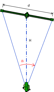
A subtense bar is one tacheometric method and the subject of this chapter. It is a physical bar with sighting targets at both ends. The distance, d, between the targets is known, Figure C-1.
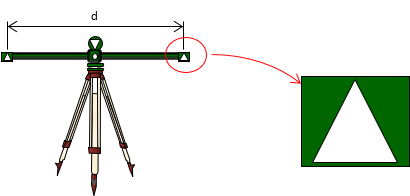 |
| Figure C-1 Subtense Bar |
The bar is set up on a tripod at one end of a line, centered on and perpendicular to it. At the other end is a transit or theodolite, Figure C-2.
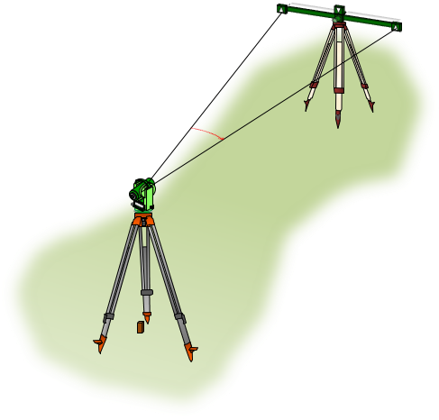 |
| Figure C-2 Set up |
The horizontal angle between the two targets is measured with the transit/theodolite, Figure C-3.
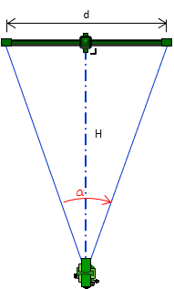 |
| Figure C-3 Measure Horizontal Angle |
The slope distance, SD, between the transit./theodolite and subtense bar is computed using Equation C-1.
 |
Equation C-1 |
c. Horizontal distance
The horizontal distance, HD, is obtained by measuring the zenith angle, Figure C-4, and using Equation C-2.
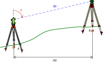 |
| Figure C-4 Slope to Horizontal |
 |
Equation C-2 |
d. Vertical distance
Although primarily used for horizontal distance determination, a subtense bar can be used for establishing elevation, Figure C-5.
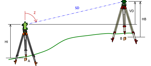 |
| Figure C-5 Elevations by Subtense Bar |
The vertical distance between the centers of the transit/theodolite and subtense bar can be computed using Equation C-3.
|
|
Equation C-3 |

If the instrument is set over a point whose elevation is known and the heights of the instrument, HI, and subtense bar, HB, are measured, the ground elevation at the subtense bar can be computed from Equation C-4.
| Equation C-4 |
2. Application
Subtense bars pre-date electronic distance measurement and were typically used when direct taping between points was not possible. They were not universally adopted as a primary distance measuring device and many surveyors have never even seen a subtense bar. They are included here, not because anyone will use one today, but because they are an interesting way of distance determination.
3. Errors
Although subtense bars are past technology, discussion of their major errors provides some insight on their use.
a. Instrumental
(1) Geometry
(a) Principle
The triangle formed by the subtense bar and instrument is a long narrow isosceles triangle. The angle measured at the instrument is small making for some weak geometry, particularly in long distances.
For example, most subtense bars were 2 meters long and transits/theodolites typically had angle measurement resolutions between 6" to 20". Solving Equation D-1 backwards means in a distance of 100 meters, the angle at the instrument is 1°08'45". An angular error of 15" changes the distance by 0.36 meters, an distance error of approximately 1/200.
(b) Behavior
Random.
(c) Compensation
Appropriate measuring instrument, repeated measurements, shorter distances.
(2) Orientation
(a) Principle
Distance determination is predicated on the subtense bar being perpendicular to the line. Most had a sighting system which helped orient the bar correctly. However, any orientation error, Figure C-5, would affect the basic geometry.
 |
| Figure C-5 Orientation |
(b) Behavior
Misorientation of the bar introduces a systematic error, Figure C-6.
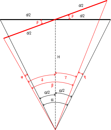 |
| Figure C-6 Misorientation Effect |
Figure D-6 uses a short slope distance, S, to more clearly show the geometry. The incorrect angle, β, is measured instead of the correct one, α. Using β in equation D-1 will introduce an error in the slope distance. Although systematic, unless the rotation angle, ρ, is known, the horizontal angle can't be corrected. Because of the rotation, the incorrect angle isn't symmetric about the slope distance. Equations C-5 and C-6 are the corrections applied to β for the left rotation of Figure D-6; they are slightly different for a right rotation.
 |
Equation C-5 |
 |
Equation C-4 |
Without knowing the rotation angle and its direction, however, it's impossible compute the corrections. Even if the rotation were known, the horizontal angle corrections would be small. For example, at 100 meters, a 2 meter long bar rotated 10° results in a horizontal angle error of 0°00'07". This would be well inside pointing and setup errors.
So even though the error is systematic, its behavior is random.
(c) Compensation
Experience; Careful equipment set up.
b. Natural
(1) Refraction and Curvature
(a) Principle
The line of sight, on which subtense bar use depends, is bent by the atmosphere and deviates from a level line due to earth curvature. The effect of each increases as does distance. However, the line of sight to each end of the bar deviates the same amount and in the vertical direction so the combined effect does not affect the horizontal angle measurement.
Is it significant enough to affect the zenith/vertical angle? Refer to Table H-1 in I. Basic Principles Chapter H. Curvature and Refraction:
| Table H-1 | ||
| Distance | α; seconds | C; feet |
| 100 | 0.5 | 0.000 |
| 200 | 1.0 | 0.001 |
| 300 | 1.5 | 0.002 |
| 400 | 2.0 | 0.004 |
| 500 | 2.5 | 0.006 |
| 1000 | 4.9 | 0.024 |
| 2000 | 9.9 | 0.096 |
| 4000 | 19.7 | 0.383 |
| 5000 | 24.7 | 0.598 |
At a distance of 1000 ft (pushing it with a subtense bar) and a 65°00'00" zenith angle (pretty steep), varying the angle 4.9" makes a difference of 0.01 ft horizontal and 0.02 ft vertical, neither of which affects the distances.
For all intents and purposes, curvature and refraction don't affect subtense bar measurements.
(b) Behavior
Systematic but negligible.
(c) Compensation
Not necessary
(2) Atmospheric conditions
(a) Principle
In addition to refraction, local atmospheric anomalies can have varying effect when the line of sight passes near a radiant surface which reflects direct sunlight pr emits absorbed heat. The line of sight in such conditions is not stable which introduces pointing errors.
(b) Behavior
Random
(c) Compensation
Select locations either removed from heat wave sources or limit observations to time of day (early) before the sun heats the intermediate surface or absorption takes place.
(3) Temperature
(a) Principle
Subtense bars are constructed of low thermal expansion alloy materials. They are not affected by temperature changes sufficiently to alter distance measurement within useful operating range.
Temperature is more an instrument operator comfort issue.
(b) Behavior
Systematic but negligible.
(c) Compensation
Not necessary.
c. Personal
(1) Set up
(a) Principle
Both the subtense bar and measuring instrument bust be set up over their respective points. This is more fully discussed in the Electronic Distance Measurement section.
(b) Behavior
Random
(c) Compensation
Careful set ups with practice will minimize the random error.
(2) Pointing
(a) Principle
The surveyor must sight both targets as accurately as possible. Longer distances are increasingly affected as the overall angle between subtense target gets smaller.
(b) Behavior
Random
(c) Compensation
Careful field procedures; Experience; Repeat angles
(3) Computations
(a) Behavior
Mistake
(b) Compensation
Due diligence.