2. Instrument Axes
a. Definitions
Instrument axes are illustrated in Figure G-4.
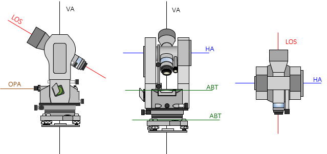 |
| Figure G-4 Instrument Axes |
The axes are also described in I. Basic Principles Chapter E. Bubbles, Axes, and Optics, Oh My!
(1) Line of Sight (LOS).
The LOS is a line through the crosshairs' intersection and objective lens optical center. It is the line along which the operator makes a sight through the telescope.
(2) Vertical Axis (VA)
The VA is the axis about which the instrument rotates in a horizontal plane.
(3) Horizontal Axis (HA)
The HA is the axis about which the telescope rotates in a vertical plane.
(4) Axis of the Bubble Tube (ABT).
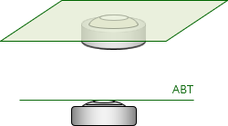
An instrument has two different types of bubbles: tube and circular.
The surface of a bubble tube is curved in the direction of its length. Its ABT is an imaginary line tangent to the center of the curved surface, Figure G-5.
 |
| Figure G-5 Tube Bubble |
A circular bubble's surface is a spherical section. Its ABT is a plane tangent to the curved surface's center, Figure G-6. From any side view, the plane appears, and behaves, as a line.
 |
| Figure G-6 Circular Bubble |
(5) Optical Plummet Axis (OPA).
The OPA is the line of sight through the optical plummet. It consists of two perpendicular segments: the observer's horizontal sight line is bent 90° through an internal prism to a vertical sight line, Figure G-7.
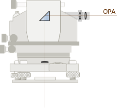 |
| Figure G-7 Optical Plummet Axis |
b. Relationships
A bubble is used to orient an instrument to gravity which should make its axes, with notable exception, vertical or horizontal For this to happen, specific geometric relationships must exist between an instrument's axes. These are:
- ABT of the tube and circular bubbles perpendicular to the VA.
- HA perpendicular to the VA
- LOS perpendicular to the HA
- OPA perpendicular to and coincident with the VA
A instrumental error exists when any of these conditions is not met. The Reversion Principle can be used to identify many of the maladjustment errors. Most can be compensated procedurally, all by equipment adjustment which makes them systematic errors.
c. Instrument Position
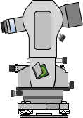
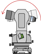
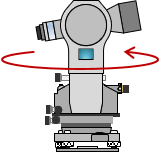
When an instrument is set up, it is either in a direct or reverse position. Position refers to axes orientations. It is changed between D and R by reversing the telescope in vertical plane and rotating the instrument in the horizontal plane, Figure G-8.
 |
 |
 |
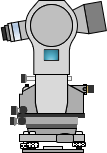 |
| (a) Direct | (b) Reverse Telescope | (c) Rotate Instrument | (d) Reverse |
| Figure G-8 Instrument Positions |
|||
This reverses the axes geometry allowing the Reversion Principle to to compensate an instrumental error either by procedure or adjustment
Another way to refer to position is by the vertical circle's placement with respect to the telescope when viewed from behind. These are called Circle or Face Left and Circle or Face Right. To keep it simple, we will use the direct/reverse designation.
Which position is direct and which is reverse? It really doesn't matter as long as the instrument geometry is reversed between the two.