3. Rod
The level rod is as important as the level instrument in a geodetic survey.Indistinct or irregularly spaced markings can defeat the purpose of using a geodetic instrument.
General characteristics of a geodetic rod are:
a. One piece
No joints which can create division spacing error. Length of a single piece rigid rod can be limited by transportation issues. If used for three-wire leveling, this also limits maximum BS and FS distances.
b. Low expansion
The structural material of the rod can vary, A in Figure H-13, but the linear divisions are on a low thermal expansion material, B in Figure H-13. Invar (also used in precise taping) is traditionally used because of its stability
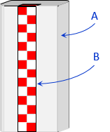 |
| Figure H-13 Rod Composition |
c. Base
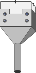
Because elevations are determined to a greater resolution than in regular leveling, it is essential that the numeric origin of the rod sit on the point observed. That is why benchmark monuments and turning points generally have domed tops - so they have a distinct high point on which to place the rod. Most geodetic level rods have a base that is small or flat with a guide, Figure H-14.
 |
|
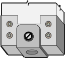
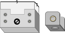
| (a) Small | (b) Flat and removable guide |
| Figure H-14 Rod Bases |
|
The rod reading at the contact point for each is 0, with readings increasing upward.
The design of the base in Figure H-14(a) forces the minimum reading to be at least the height of the base above the ground. This is to ensure the LoS is above the boundary layer that is subject to residual heat waves not visible to the naked eye. The FGCS geodetic leveling specifications require the LoS be no lower than 0.5 m on the rod.
The rod base in Figure H-14(b) is flat but has a detachable guide to facilitate setting up on a dome point benchmark or turning point without sliding off.
d. Distinct markings
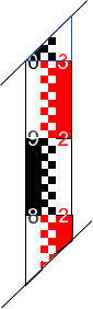
A geodetic rod is wider than its basic leveling counterpart to have room for distinct makings and numbering. Two metric rod examples are shown in Figure H-15.
 |
 |
| (a) Example 1 | (b) Example 2 |
| Figure H-15 Metric Rods |
|
The rod design in Figure H-15(a) is used for three-wire or micrometer leveling
- Numbers on the right are full meters; on the left are 0.1 m
- Alternating colors are used every 0.1 m
- Rod divisions are 0.01 m
The rod design in Figure H-15(b) is used with an inverted image instrument.
- The rod image appears upright when viewed through the instrument
- Numbers are cm
- Rod division interval is 1 cm
- Dual scale rod; scales are offset a constant amount, 279.5 cm in this example
- Both scales are read as a check
These are just two examples of many different rod designs. While there are rods with English linear units, most geodetic leveling is done in the metric system.
For formal geodetic leveling the rod must be calibrated.
e. Bipod
The rod must be held vertically long enough for the instrument person to take and verify his/her readings. This can take a bit of time when three-wire leveling or using an optical micrometer. A set of bipod legs, with quick release locks, are attached to the back or top of the rod, Figure H-16.
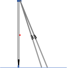 |
| Figure H-16 Bipod |
These, with the circular bubble on the rod, make set up quick and stable.