D. Multi-Center Horizontal Curves
1. General
A multi-center curve consists of two or more back-to-back curves that are tangential. The simplest consists of two curves either in the same direction (compound) or opposite directions (reverse), Figure D-1.
 |
 |
| a. Compound curve | b. Reverse curve |
| Figure D-1 Multi-center curves |
|
Multi-center curves provide greater design flexibility. For example, Figure D-2 shows a typical cloverleaf freeway interchange.
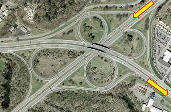 |
| Figure D-2 Cloverleaf interchange |
To travel southeast, southwest-bound traffic changes direction approximately 280° using the southwestern loop. This is accomplished using a flat curve for initial deceleration, followed by sharper curves for most of the direction change, and finally shallower acceleration curves. Figure D-3 shows the southwestern loop with overlaid circular arcs.
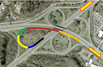 |
| Figure D-3 Multiple curves |
Using a multi-center curve makes the interchange more space efficient; consider how much area would be needed for a single radius curve in this situation.
A reverse curve also provides design flexibility, particularly in tight areas.
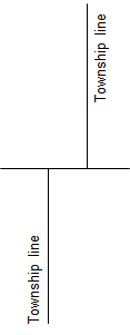
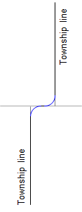
For example, in Public Land Survey (PLS) states, north-south Township lines were offset along Standard Parallels to account for meridian convergence, Figure D-4a. Roads commonly followed Section and Township lines. At an offset Township line, a sharp left turn shortly after a sharp right turn was perfectly acceptable at horse drawn wagon speed, Figure D-4b. As vehicle speeds increased, flatter curves were necessary but had to fit between the Township line segments. This could be done using a reverse curve, Figure D-4c.
 |
 |
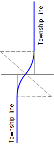 |
| a. Convergence offset | b. Low speed curves | c. High speed curves |
| Figure D-4 Offset Township lines |
||
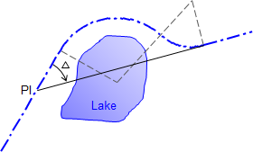
A reverse curve can also be used to work an alignment around an obstruction. Figure D-5 shows what, were it not for the presence of a lake, would be a simple curve situation .
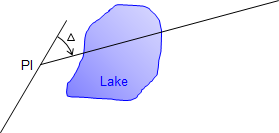 |
| Figure D-5 Obstruction |
Neither a long nor short radius single curve will miss the lake. However, a curve to the right could be fit to an extension of the incoming tangent followed by a curve to the left to meet the original outgoing tangent, Figure D-6.
 |
| Figure D-6 Working around obstruction |
If multi-center curves are so flexible, why don't we see more of them?
Primarily because of the curvature change at each curve-to-curve transition.
On a simple curve, once the driver sets the steering wheel angle, it is maintained through the entire curve. A multi-center curve requires a steering wheel angle change at the beginning of each curve. Except for a reverse curve, it may not be visually apparent where one curve ends and the next begins. This makes it easy to over- or under-shoot successive curves.
Traveling around a circular arc introduces centrifugal force which pushes the vehicle (and its occupants) to the outside of the curve. The sharper the curve or the higher the speed, the greater the force. One way to offset this centrifugal effect is to use superelvation - pavement cross-slope inclination. As a vehicle traverses differing radii curves, different superelevation rates are needed. Superelevation change should be introduced gradually or passengers may feel like they are being tossed to the side. This is more pronounced with a large radii difference from one curve to the next. On a reverse curve the condition can be worse since the cross-slope direction must be changed.
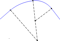
Figure D-7 shows a three-center curve system with 5 section view labels.
 |
| Figure D-7 Three-center curve |
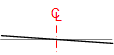
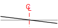
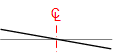
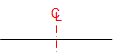
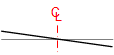
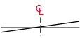
Table D-1 depicts the steering wheel angle and superelevation at each section view going through the curve system.
| Table D-1 | ||
| Section | Steering Wheel | Superelevation |
| A-A | 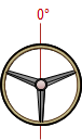 |
 |
| B-B | 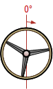 |
 |
| C-C | 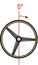 |
 |
| D-D | 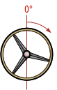 |
 |
| E-E | 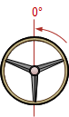 |
 |
Note that the greatest wheel angle and superelvetion occur on the third curve and must be removed entirely when the exit tangent is reached. That abrupt change could cause safety and comfort issues.
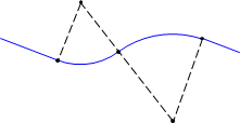
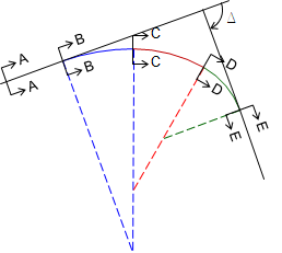
A reverse curve provides an additional chanllenge, Figure D-8 and Table D-2.
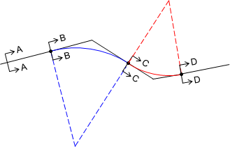 |
| Figure D-8 Reverse Curve |
| Table D-2 | ||
| Section | Steering Wheel | Superelevation |
| A-A | 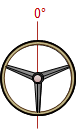 |
 |
| B-B | 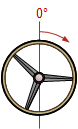 |
 |
| C-C | 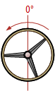 |
 |
| D-D | 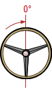 |
 |
At the point of reverse curvature, the steering angle must be changed to the other side. The superelevation also changes direction so the vehicle is "rolled" from one side to the other. Coupled with superelevation, the centrifugal force changes direction. All-in-all quite a bit of stuff going on, especially when the vehicle is cruising along at a good rate.
So while multi-center curves provide greater design flexibility, they do have drawbacks. particularly in high speed situations. Except for special cases such as interchanges, their use should be limited to lower speeds with reasonable radii differences.