B. Angles and Directions
1. Take a Breath...
An angle is between two lines; a direction is similar except one of those lines is a meridian. An angle only relates one line to another; a direction relates all lines referenced to the same meridian. Directions are a fundamental concept in horizontal positioning.
Starting with a direction for one line, directions of other connected lines can be computed using the horizontal angles linking them. Directions and angles are added or subtracted dependent on the type of horizontal angle (interior, deflection, etc), turn direction (clockwise or counterclockwise), and direction type (bearing or azimuth).
We can also go at it in reverse: given line directions, compute the angle relating the lines (interior, left/righ, deflection, etc). This comes in handy when summarizing the results of a traverse adjustment which will be covered in a later topic.
Every surveyor should be able to convert between directions and angles. That sounds like an easy skill to master, however it does take some practice. A good approach for the beginning (and some seasoned) surveyors is to draw a sketch. This allows you to visualize what you are statring with, what you're solving for, and the correct math to connect the two.
When computing directions from angles or vice versa there are a few things to remember:
- the releationship between forward- and back-bearings (same angle, opposite quadrant) and forward- and back-azimuths (±180°).
- angles to the right are positive (added), left are negative (subtracted)
- meridians are parallel at all points (plane surveying)
There are a few common pitfalls to avoid and they are coverd in the Chapter Summary after the examples problems. This is to give you an opportunity to expereince them.
2. Directions from Angles
a. Bearings
(1) Example 1
The bearing of line GQ is S 42°35' E. The angle right at Q from G to S is 112°40'. What is the bearing of the line QS?
Draw the sketch in parts starting with what is given.
|
|
Add the meridian at Q and label angles,
|
|
At Q, the bearing to G is N 42°35' W.
Subtracting 42°35' from 112°40' gives the angle, β, from North to the East for line QS.
Bearing QS = N 70°05" E
(2) Example 2
The bearing of line LT is N 35°25' W. The angle left at T from L to D is 41°12'. What is the bearing of the line TD?
Sketch:
 |
Add meridian at T and label angles
|
|
At T the bearing TL is S 35°25' E.
The bearing angle, σ, is 35°25' + 41°12' = 76°37'
Bearing TD = S 76°37' E.
b. Azimuths
(1) Example 1
The azimuth of line BP is 109°56'. The angle right at P from B to J is 144°06'. What is the azimuth of line PJ?
Sketch:
|
|
At P, add the meridian and extend the line BP
|
|
The azimuth of the extension is the same as the azimuth of line BP.
The azimuth of line PB: 109°56' + 180°00'= 289°56'.
Since 144°06' is to the right (+), add it to the azimuth of PB to compute azimuth of PJ: 144°06' + 289°56' = 434°02'
|
|
Why is the azimuth greater than 360°? Because we've gone past North.
To normalize the azimuth, subtract 360°00': 434°02' - 360°00' = 74°02'
(2) Example 2
The azimuth of line WX is 258°13'. At X the deflection angle from W to L is 102°45' L. What is the azimuth of line XL?
Sketch:
|
|
A deflection angle is measured from the extension of a line. The azimuth of the extension is the same as that of the line. To compute the next azimuth, the deflection angle is added directly to the previous azimuth.
Because this is a left deflection angle, you would add a negative angle.
Add meridian at X:
|
|
Azimuth XL = 258°13' + (-102°45') = 155°28'
3. Basic Angles from Directions
a. Bearings
(1) Example 1
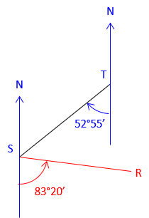
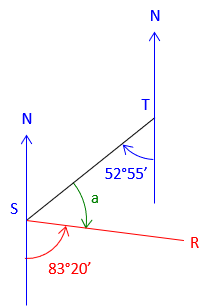
The bearings of lines TS and SR are S 52°55' W and S 83°20' E, respectively.
What is the angle right at S from T to R?
| Start with the given information | Label whet we're determining |
 |
 |
| Add the back-bearing TS | |
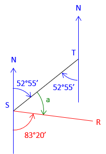 |
a = 180°00'-(52°55'+83°20') = 43°45' |
(2) Example 2
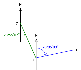
The bearing of ZU is S 23°55’07” E; the bearing of UH is N 78°05’00” E.
What is the defelction angle at U from Z to H?
| Start with the given information. | Label what we're determining |
 |
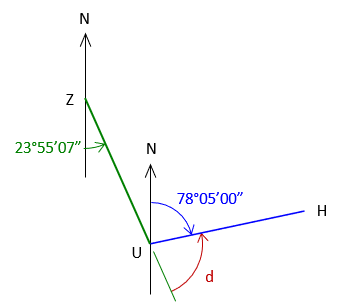 |
| Add the back-bearing UZ | |
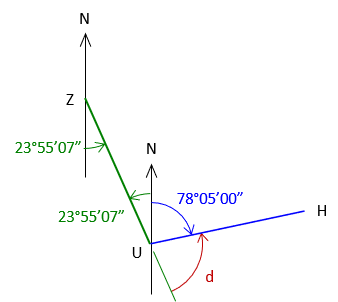 |
d = 180°00'00"-(23°55'07"+78°05'00") = 77°59'33" A deflection angle must have a suffix to indicate turning direction defl angle = 77°59'33" L |
b. Azimuths
(1) Example 1
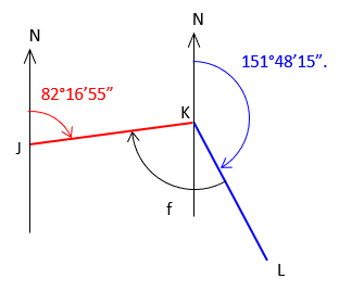
The azimuths of lines JK and KL are 82°16'55" and 151°48'15", respectively.
What is the angle right at K from J to L?
| Start with the given information. | Label what we're determining. |
 |
 |
| Add the back-azimuth for line KJ | |
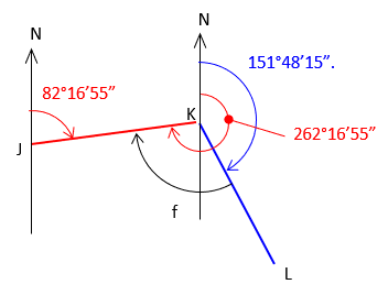 |
f = 262°16'55"-151°48'15" = 110°28'40" |
(2) Example 2
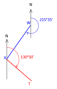
Azimuth of line WX is 215°35’; azimuth of line XT is 130°50’
What is the deflection angle at X from W to T?
| Start with the given information. | Label what we're determining. |
 |
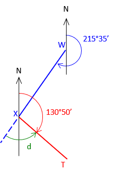 |
| Extend WX through X and add the azimuth of WX | |
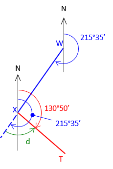 |
d = 215°35'-130°50' = 84°45' A defl angle must end with an L or R suffix to indicate turn direction. defl angle = 84°45' L |
4. Angles from Directions - Traverse-based
a. Angles from Bearings
Given bearings going counter-clockwise around a loop traverse, compute the interior angles at each point. Perfom a math check at completion.

It doesn't matter where to start or in what order or direction to compute the interior angles.
Drawing sketches helps visualize how to combine the bearings at a point to compute the angle.
| At point R | |
 |
BrngRU = S 15°24'47" E AngleR = 71°43'30"+15°24'47" = 87°08'17" |
| At point S | |
 |
BrngSR = N 71°43'30" E AngleS = 108°00'00"-(35°25'40"+71°43'30") =72°50'50" |
| At point T | |
 |
BrngTS = N 35°25'40" E AngleT = 72°48'15"+35°25'40" = 108°13'55"
|
| At point U | |
 |
BrngUT = S 72°48'15" E AngleU = (180°00'00"-72°48'15")+15°00'35" = 122°12'20" |
| At point V | |
 |
BrngVU = S 15°00'55" W AngleV = 88°25'02"-15°00'35" = 73°24'27" |
| At point W | |
 |
BrngWV = N 88°25'02" W AngleW = 360°00'00'-(88°25'02"+15°24'47") = 256°10'11" |
Math check
Six sided polygon: Σ(Int angles) = (n-2) x 180° = (6-2) x 180° = 720°
Σ(Int angles) = 87°08'17"+72°50'50"+108°13'55"+122°12'20"+73°24'27"+256°10'10" = 720°00'00" check
b. Deflection Angles from Azimuths
(1) Process
Because a deflection angle is the angle from the projection of the previous line to the next line, it is the difference between the azimuths of the two lines. For example, in the diagram below the deflection angle Y is the difference between the outgoing azimuth (AzYZ) and the incoming azimuth (AzXY).

defl angY = AzYZ-AzXY
By subtracting the incoming azimuth from the outgoing azimuth, the correct mathematical sign is returned for the deflection angle. In the previous diagram, the deflection angle would be to the left. In the following diagram:

the deflection angle is to the right.
Whether you remember to subtract the incoming from the outgoing azimuth or not, the important thing is that the deflection angle is the difference between the azimuths. As in many survey computations, a properly drawn sketch is extremely beneficial.
(2) Example Azimuths to Deflection Angles
Given azimuths going clockwise around a loop traverse, compute the deflection angles in the same travel direction. Perfom a math check at completion

| At point L | |
 |
 |
| At point M | |
 |
 |
| At point N | |
 |
 |
| At pointr O | |
 |
From the sketch, the deflection angle should be to the right so the difference should be positive. |


Math check:
For a non-crossing loop traverse, the deflection angle sum should be ±360°

5. Summary
Converting between angles and directions isn't difficult, but there are a few things someone new to the computations needs to watch out for.
(1) Incorrect bearing quadrant.
This usually happens when the sketch isn't correctly drawn. In the diagram below, the surveyor assumed line JK was in the NE quadrant.

The bearing angle is the difference between the back bearing and the angle J. Based on his sketch, the surveyor recorded the bearing JK as S 8°19'15" E while it really is N 08°19'15" W. While a sketch helps, an incorrectly drawn one can lead to wrong answers.
(2) Bearing angle exceeds 90°
In this example, the surveyor computed the bearing angle as the sum of the back bearing angle and angle M, recording the bearing of line MN as N 91°05'45" E

When a bearing angle exceeds 90°, the line crosses into the adjacent quadrant. Line MN's correctly written bearing is S 88°54'15" E
(3) Using the East-West line
Directions are always referenced to a meridian, a North-South line. When performing calculations, angles should never be computed from the East-West line as it may lead to confusion. Students working with directions early on tend to break up angles into smaller parts, often computing parts from the East-West line. For example, in the following sketch, an intermediate calculation may be:


Bearing line RS is N 70°19'30" W from:

Using the East-West line adds another layer of calculations and potential error. One way to avoid using it, leave the East-West line off the sketch.
(4) Math mistakes
Most errors are angle addition or subtraction mistakes. Angles are a mixed unit system, deg-min-sec. They are also a mixed base susyem: minutes and seconds both max out at 60 while degrees are unlimited, Manual calculatoins errors are usually the result of either or both factors. Calculators with built-in degree conversion or direct deg-min-sec manipulation capabilities help reduce the problem, providing the user knows how to use the calculator. Although they can help simplify and streamline calculations, the surveyor should stil be capable of manual angle calculations.