2. Plotter Principles
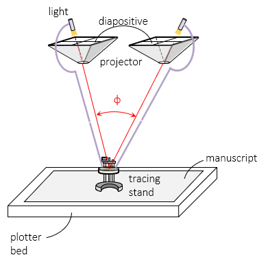
An optical plotter has a movable light source in each projector, These illiminaute only a part of the diapositve. Each light source is connected to a tracing stand. The light projects the same image from both diapositives, Figure G-1, onto the tracing stand's platten, the center of which is a small illuminated dot.. The tracing stand sits on the manuscript on whilch the map is compiled. The plotter bed is a heavy piece of slate or similar material providing a solid stable base.
 |
|
Figure G-1 |
The illuminated dot on the platten appears to float in the 3D image, Figure G-2. Raising and lowering the platten causes the dot to float above (A), on (B), or below (C) the model surface.The vertical platten movement can be directly converted into elevation.
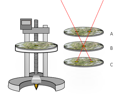 |
| Figure G-2 Tracing Stand and Floating Dot |
It is called an optical plotter because the floating point location is a function of the parallactic angle between the image projection lines. It is not the angle between the connection rods to the lights.
The operator adjusts the platten height until the floating dot appears to sit on the ground - this is an optical solution of the parallax equations. A pencil lead or scribe is located directly beneath the platten dot so by moving the tracing stand while keeping the floating dot on the ground (tracing the contour), the operator can trace a contour line on the manuscript. Planimetric features can be mapped similarly.