3. Types of Plotters
a. Optical
The most prevalent optical plotter was a Kelsh-stlye plotter, Figure G-3. It used full size 9"x9" diapositives. Its predecessors include the Multiplex and Ballplex potters, both of which used reduced size diapositives limiting their plotting accuracies.
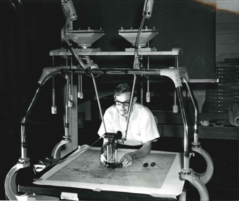 |
| Figure G-3 Kelsh-style Plotter |
Notice the operator in Figure G-3 is working in a dark room: The only part of the model illuminated is that part projected onto the platten. Because the plotter is an open design, ambient light would wash out the 3D view on the platten.
To see the model in 3D, the operator's right eye must see only the right image, the left eye the left image.The reason was discussed in the previous chapter. On a steroplotter, one of three different systems was used to force each of the operator's eyes to view the correct image projection. Anaglyphic (red & blue lenses) and Polarized systems were described in the previous chapter. Another common system used synchroized rotating shutters. Each projector had its own shutter whose rotation was matched to one on the tracing stand.When one shutter set was closed, the other was open so only one eye saw its image at a time. The rotation was fast enough that the operator wasn't aware of the on-off shutter sequence. The shutter system was preferred because color photogtrahphy could be used (unlike the Anaglyphic System) and the image was brighter since no filters were used.
b. Mechanical
These are newer enclosed instruments, Figure G-4, which use precise optics to shorten and better control optical projection geometry.
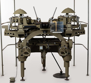 |
| Figure G-4 Mechanical Plotter |
The operator sits and views the 3D model though a binocular system using prisms so filters and shutters aren't needed. Because it is an enclosed system, it needn't be operated in darkroom conditions.
The diapositives are mounted in carirers and can be moved horizontally in concert to view a specific overlap area. The operator uses handwheels (left-right, front-back) to control this motion. This takes the place of moving a tracing stand across the plotter bed.
Instead raising/lowering a platten with its illumiated dot, internal prisms are rotated to change the floating dot elevation, similar to a parallax bar. This vertical motion is operater-controlled using a footwheel. This makes floating dot placement more precise than possible with an optical plotter, Figure G-5.
 |
|
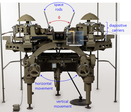
Figure G-5 |
Two spacerods connect the diapositive carriers with a pivot point in front of the operator. As the hand/foot wheels are turned, the spacerods move to recreate the image's parallactic angle. This space rod operation creates a mechanical connection between the diapositives and operator controls, hence the name mechanical plotter.
The map is compiled on an adjacent table using either a mecahnically connected plotting arm (pantograph) or a digital plottor.
c. Opti-Mechanical
This type is a cross between an optical and mechanical plotter having chracteristics of both, Figure G-6.
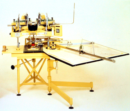 |
| Figure G-6 Opti-Mechainical Plotter |
The example in Figure G-6 uses a tracing stand similar to an optical machine but connects it to the diapositives using space rods like a mechanical one. The diapositives do not move and the operator views the model using a binocular/prism system maintaining correct optical geometry.
This example uses a pantograph connected to the tracing stand to directly plot the map.
d. Digital Integration
Unlike an optical stereoplotter, mechanical and opti-mechanical ones are highly adaptable to computer integration and digital data capture. Figure G-7 shows a collection of digitally-integrated mechanical plotters.
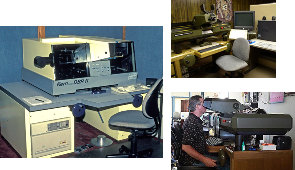 |
| Figure G-7 Digital Mechanical Plotters |