2. Applications
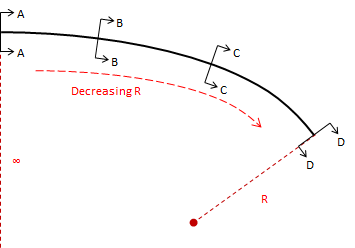
a. Direction transition
Because curvature is introduced progressively, the driver gradually changes the steering wheel angle allowing a more natural direction transition.
 |
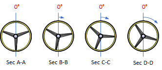 |
| Figure E-2 Steering wheel angle along a spiral |
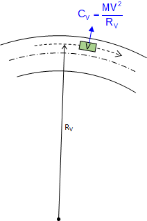
b. Force balancing
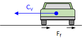
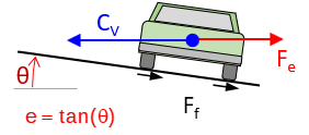
A vehicle traveling a curved path at constant velocity is subject to a centrifugal force, CV, pushing it (and its occupants) to the outside of the curve, Figure E-3(a). If the pavement cross-slope is flat, only the friction between the tires and road surface prevents the vehicle from sliding off the curve, Figure E-3(b). In low friction situations (rain, snow, etc), sliding will occur at lower speeds. Banking the pavement cross-slope into the curve, Figure E-3(c), allows part of the vehicle weight to work with friction to offset the centrifugal force. This banking is called superelevation, e.
 |
 |
| (b) Flat pavement cross-slope | |
 |
|
| (a) Centrifugal force | (c) Superelevation added |
| Figure E-3 Balancing forces |
|
At the right combination of vehicle speed and superelevation, friction does not come into play - the pavement can be ice covered and the vehicle will not slide off the curve.
With a circular curve, centrifugal force is theoretically introduced immediately upon curve entry. This doesn't typically happen because it takes the driver some distance to change the steering wheel angle from straight ahead to full-turn. Deciding where to begin rotating the cross-slope from flat and how quickly to reach full superelevation requires some compromises.
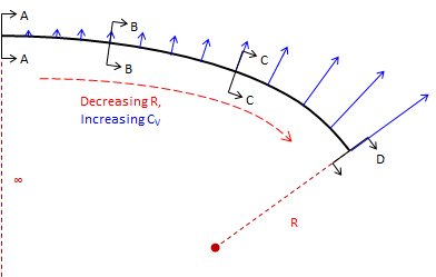
A spiral helps because its decreasing radius increases centrifugal force gradually, Figure E-4, so superelevation can be introduced at a corresponding rate keeping forces balanced.
 |
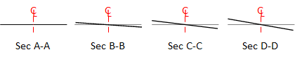 |
| Figure E-4 Cross-section along a spiral |
It is primarily because of this force balancing characteristic that spirals are used in high-speed railroad alignments. More on that in the yet-to-be-developed Superelevation chapter.
c. Design flexibility
Combining spirals with (or without) intermediate circular arcs allows greater design flexibility particularly in limited spaces and where large directional changes are involved. Consider the two alignment segments in Figure E-5(a) which are to be connected via a cloverleaf interchange. Traveling North to West, the directional change is 270° degrees. Figure E-5(b) shows three alternative curve systems to connect the two alignments. This interchange type is used extensively in high speed situations where the driver must decelerate, negotiate a large direction change, then accelerate to match traffic. It should be a smooth and surprise-free driver experience.
 |
 |
| (a) Intersecting alignments | (b) Alternative curve systems |
| Figure E-5 Cloverleaf interchange | |
The green system is a single tangent circular arc. Even though it is a relatively sharp curve, it takes up the most space (to take up less space, it would need to be even sharper). Its primary shortcomings are the tangent-curve-tangent transitions and centrifugal force condition requiring a lower speed and higher superelevation.
The red system is a five-center compound curve using consecutive curves of varying radii. The concept behind this application was discussed in Chapter D. Multi-Center Horizontal Curves. While better than the single curve and taking up less space, it can still be problematic at the curve-curve transitions since the forces can change substantially unless speeds are reduced.
The blue system is a spiraled horizontal curve: an entrance spiral into a circular arc into an exit spiral. In this example, this is a symmetric system with entrance and exit spirals mirror images of each other, although that needn't be the case. Not only does this curve system provide the smoothest speed and direction changes, it is the most comfortable and takes up the least space.